In this tutorial, you will be able to see in detail all the steps involved in building the Magnorail display module that we present during exhibitions. You will also find many tips and tricks to ensure a trouble-free start-up.
Here are the different steps of this tutorial:
- presentation of the project, the module size 75×35 cm and its woodwork
- products used
- assembly and installation of the track and the motor module
- presenting and assembly of the return loop
- assembly and installation of the chain
- installation of a cover for the track using cardboard or plastic sheeting
In short, a fairly simple programme but one that requires a certain amount of organisation, so let’s look at it in detail.
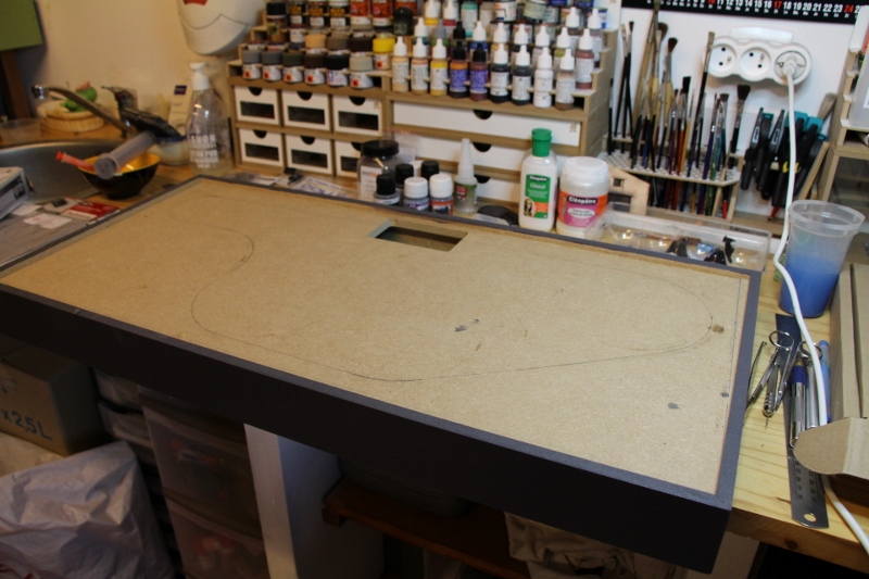
First of all, here is a quick presentation of the project on a plan drawn on the fly but which we recommend to scale.
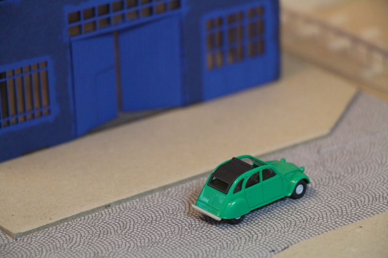
It is a city setting with a slalom through urban buildings (MKB garage, and Joswood city building in this particular case)
The length of the circuit is approximately 180 cm and will be operated by a medium speed motor to move cyclists and vehicles.
The circle at the top left (A) is the return loop, which we leave visible as well as the engine module (i.e. the whole dotted part). The big part in the centre will be dedicated to the Joswood corner building and then a park with some trees. The lower triangle will be dedicated to a square with a statue/monument…
This step remains important because it allows :
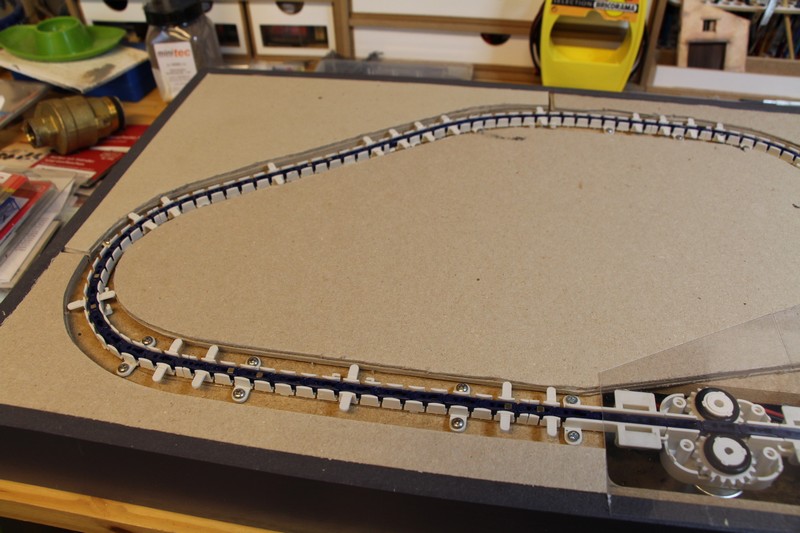
- Positioning the motor module (B) preferably in a straight line and always in the middle of the circuit so that the chain length is evenly distributed before and after.
- Drawing the curves (C), here we have a total of 4 curves + the return loop. This is a lot, but with a radius of 8 cm there is no problem. Therefore, we recommend a radius of at least 8 cm to reduce the friction between the chain and the track.
- Incorporating a return loop, which will take the strain off the engine, especially on a circuit with many bends.
- Integrating the elements of the setting (building, road, vegetation)

The woodwork is made of MDF, the top is integrated 8 mm below the 0 level, which corresponds to the height of the chain. A 100×60 mm rectangle has been cut out for the motor to fit through.
Products used :
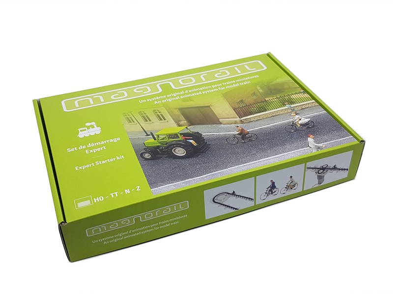
For the animation of the module, we will use a complete Magnorail pack with 2 cyclists ref BF-2 as well as a set of 8 cursors for the movement of the vehicles ref ES-1
You can see in detail the composition of the pack in our Products section
Assembling and laying the track :
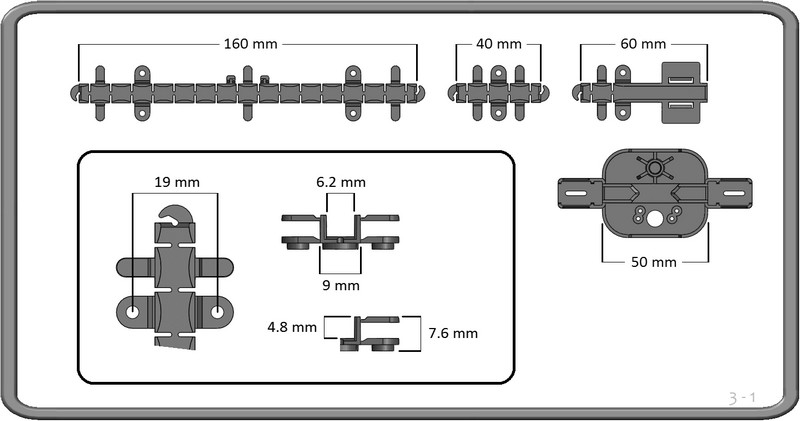
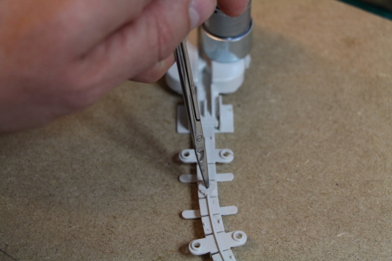
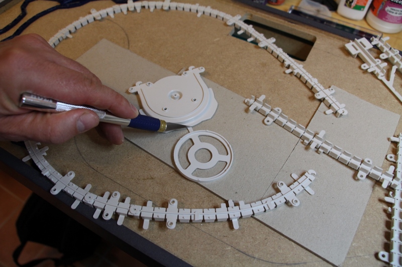
We will start by creating the track using the 160 or 40 mm flexible coupons supplied in the pack.
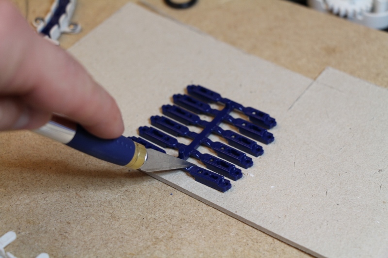
Nothing very complicated, we remove the coupons from the cluster with a classic modeler’s knife since the plastic is flexible.
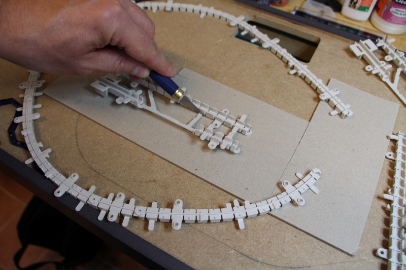
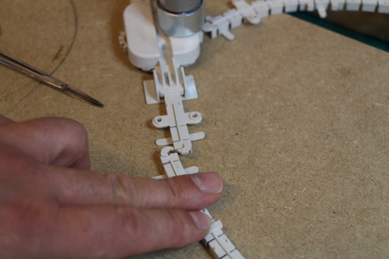
Then you assemble the coupons together, it’s child’s play at this point!
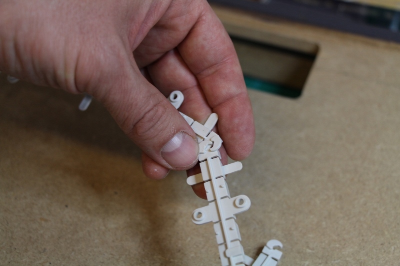
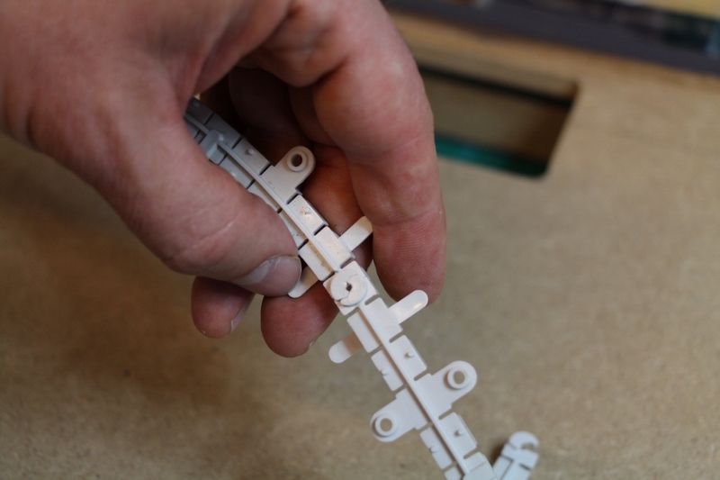
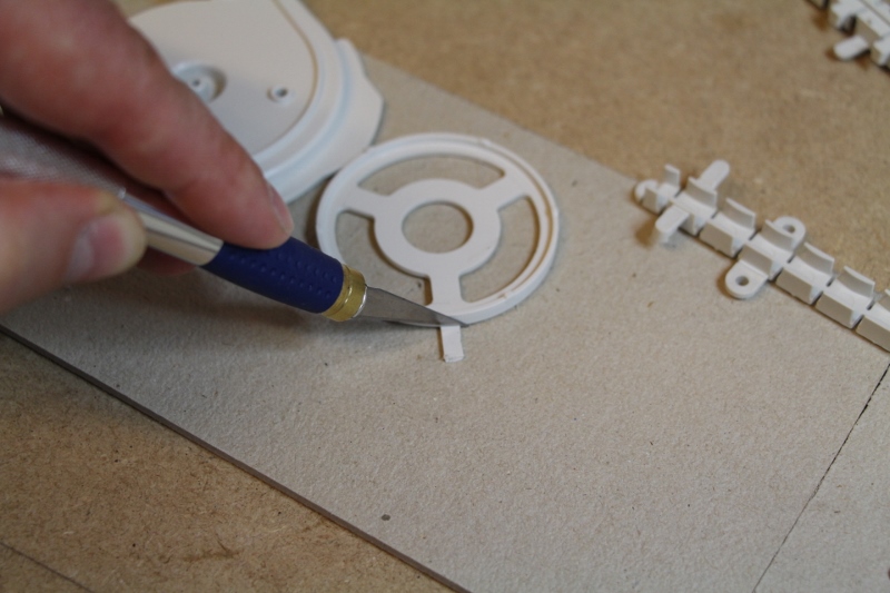
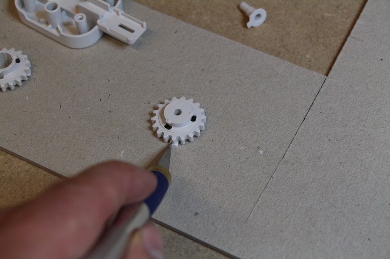
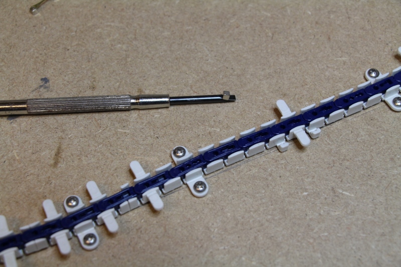
In the event of a mistake, dismantling the track is simple using a sharp chisel or small screwdriver. This will be used to remove the connection system as shown.
If, at the end, you realise that the coupon is too big or too short…
No problem! With the clusters you have 1/4 coupons, these will be useful to finish your loop, otherwise you can cut a piece of the track, remove the extra connection and join the two.
The role of the track is only to guide the chain, so you will have to make sure that the track is laid correctly, with curves or bends without breaks.
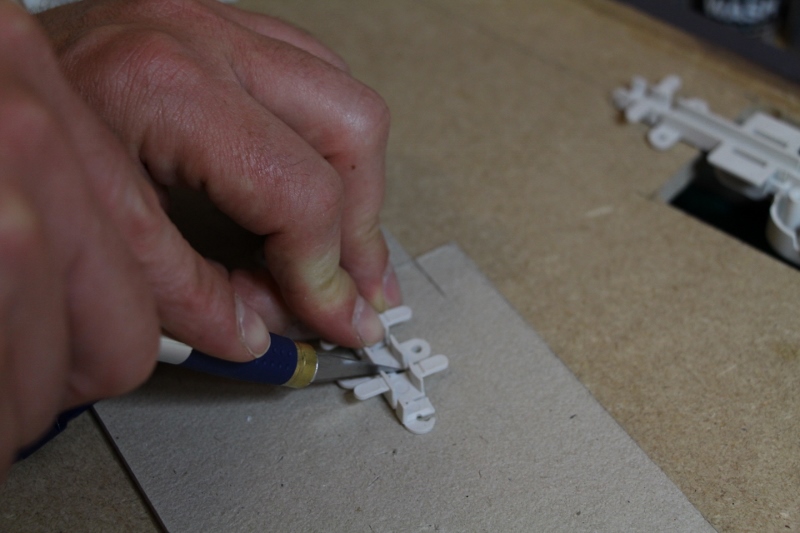
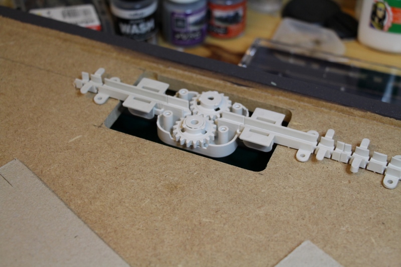
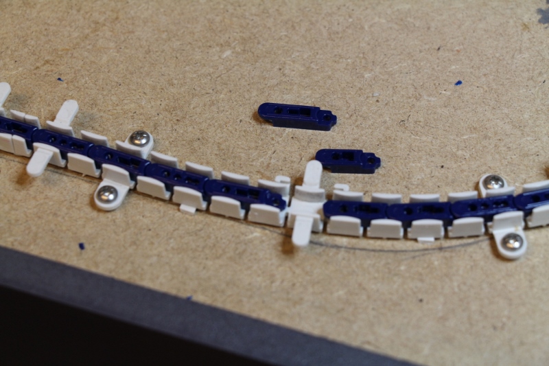
Fix the track to the support with the screws (supplied in the set). In this case, cut the piece of track close to the screw holes (see left coupon in the photo above).
If you are renovating an old module, you can also dig a 9×8 mm trench in your support and glue the track to the bottom.
We will continue with the presentation of the return loop and the engine.
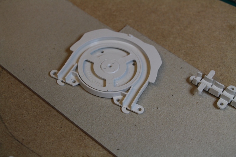
The return loop is a wheel of about 7 cm in diameter that is placed on a support.
This element is very interesting for half turns “on the spot” without friction constraints between the chain and the track.
Let’s look at all of this in detail…
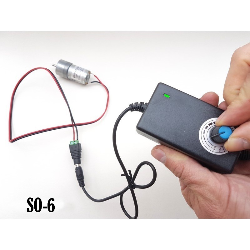
Regarding the motor module, the new Magnorail set offers 3 different motorisations (slow speed for boats, medium speed for cyclists and fast speed for cars)
Here is the average speed, note that the speed of the 12V DC motor can be controlled using our variable power supply ref SO-6. This is a nice way to find the speed that suits you.
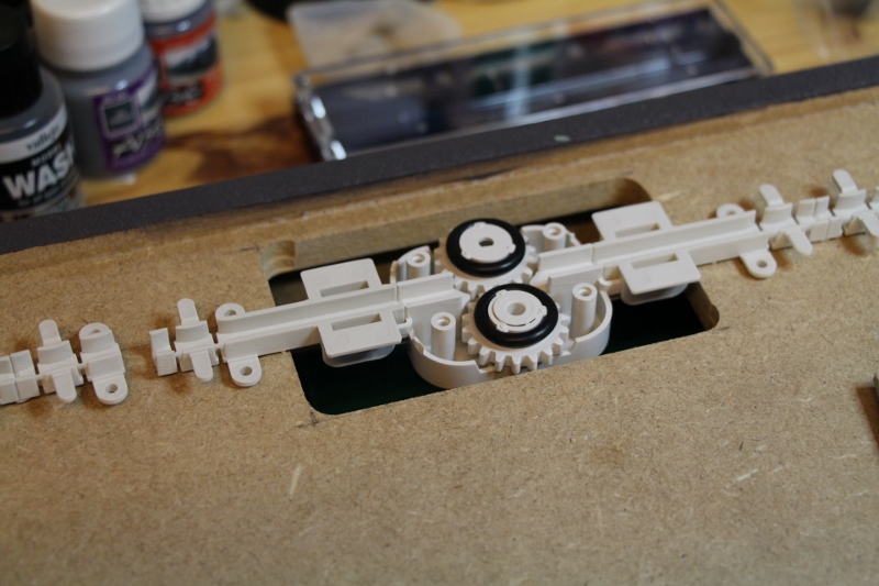
1/ Removing the gears
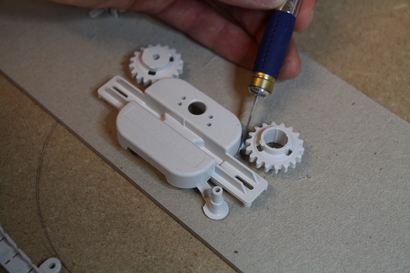
2/ The wheel parts are carefully deburred to avoid blocking during rotation
3/ The motor is then fitted together with its reduction system. Simply screw it in with the screws provided.
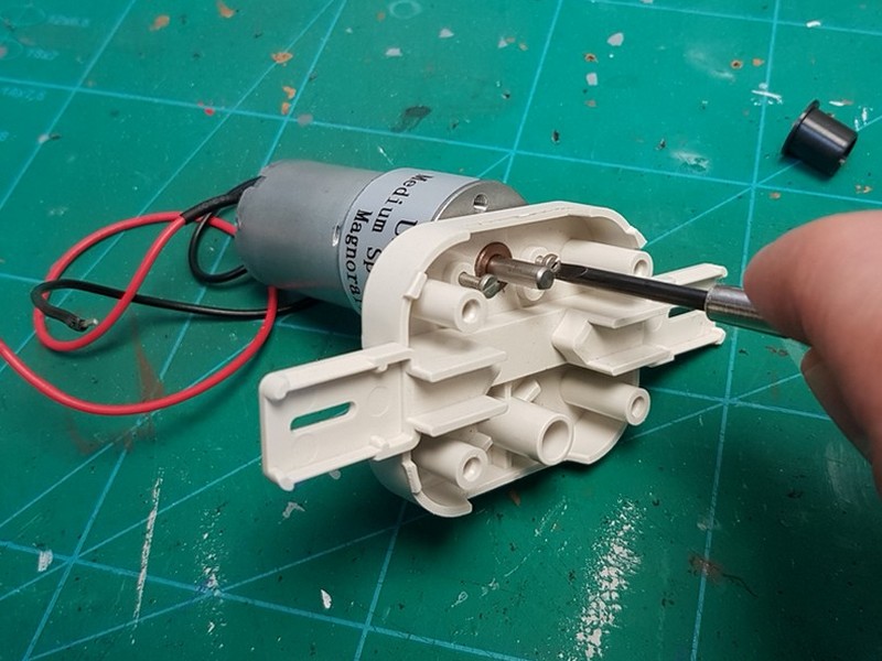
4/ Push the gear wheel on the motor axle as far as it will go (it has a detent). Be careful, you have to force it!
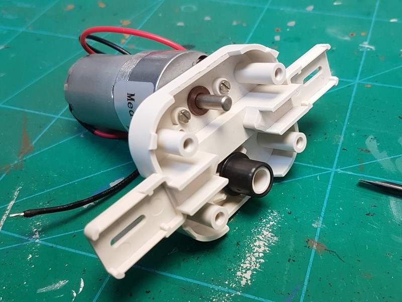
Then we put the nylon bearing on the shaft of the counter wheel
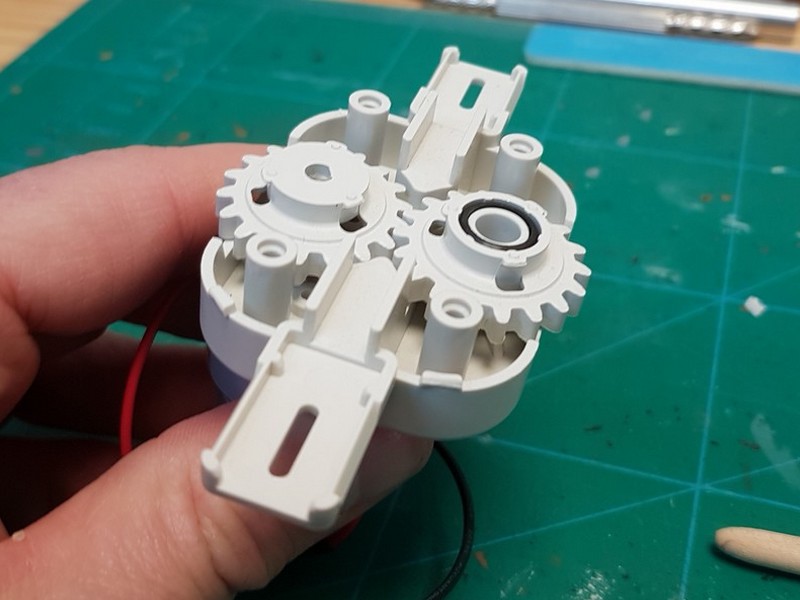
5/ The second gear is installed, you just have to add the conical plug. I recommend that you push it in completely but without forcing it so as not to slow down the proper rotation of the gears. The reduction system of the engine may wear out quickly and may make more noise! Do not neglect this.
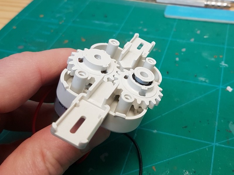
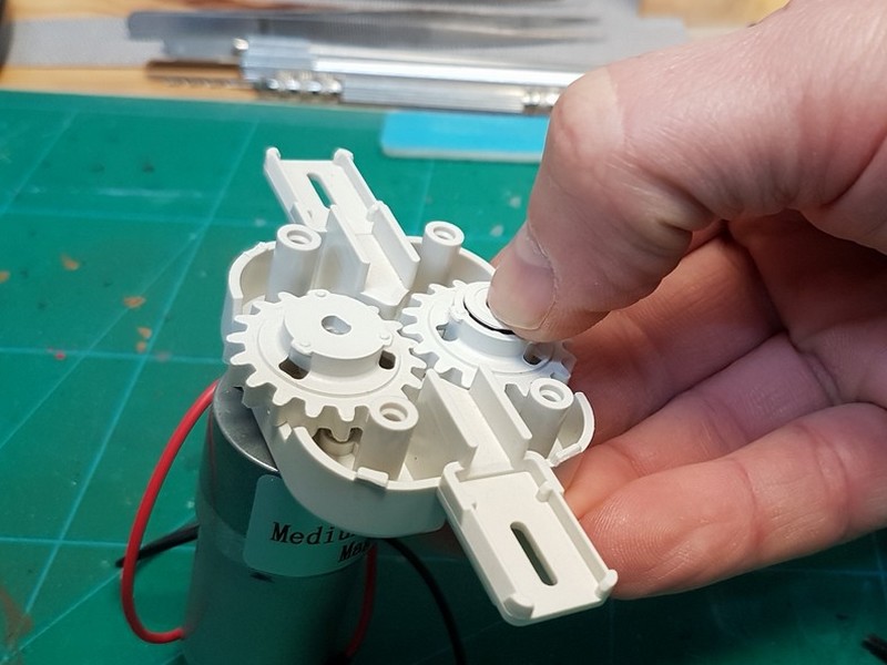
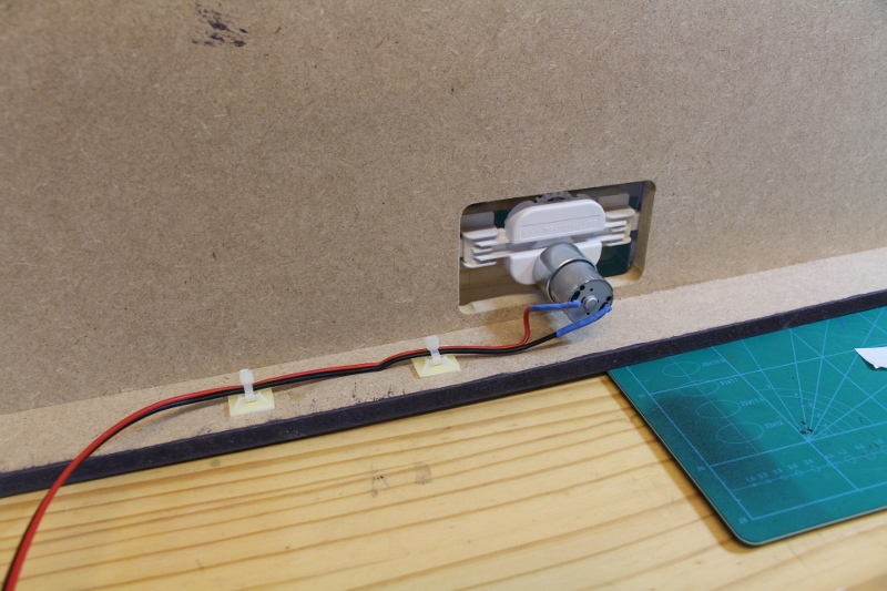
Here the engine is presented on its stand.
We will now look at the Magnorail chain.
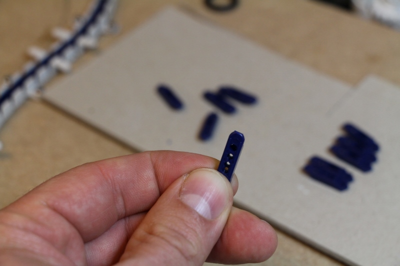
Made from a plastic with a smooth, slippery surface, the chain links are presented in a cluster. As the link of the cluster is at the rounded part of the link, each link should be carefully deburred to maintain the articulation and flexibility of the chain and to avoid any braking or blocking on a curve.
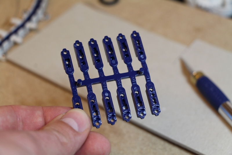
Freshly cut link of the chain
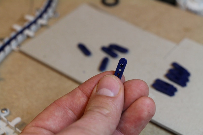
The same link deburred with a knife or file. The end is well rounded.
Note that the rounded end is intended to be in the “forward” direction of traffic.
When assembling the links, it is better to do it on a cardboard board rather than directly in the track because it is difficult to plug each link into each other in a straight line. Doing so at a 45° angle is easier, and then they can be put back in a straight line.
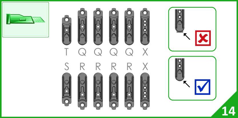
There are different types and sizes of links (Q, R, S, T and X see below) and especially different types of cavities for the magnets (14 mm in our case). It is therefore necessary to plan the position of your cyclists and vehicles on your circuit.
Then we’ll see what the rule is for your cyclist or vehicle slider to stick to it.
Now let’s see how to correctly place the magnets in the chain and on the sliders to get the correct movement of the vehicles.
As explained in the instructions, the magnets must be positioned every 14 mm, which is equivalent to placing one magnet in a Q link and another in an R link.
This 14 mm pitch is only valid for cyclists and vehicle sliders but not for tandems, three-wheelers and small sliders for N or Z vehicles for example.
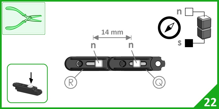
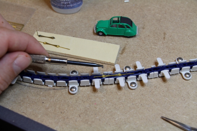
For installation, you can place two magnets on top of each other as shown in the instructions, this allows you to insert the magnet with the correct polarity. You can also let the magnet stick by itself on a flat screwdriver and then insert it into the link.
Naturally, as many sets of magnets as you wish can be installed. For this module, I installed 6 sets of magnets, well distributed, so that the position of the cyclists or vehicles can be varied during the start-up.
I advise you to put your cyclist or slider down right away to check that the polarities are correct.
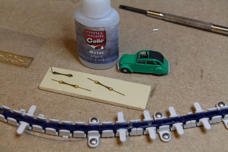
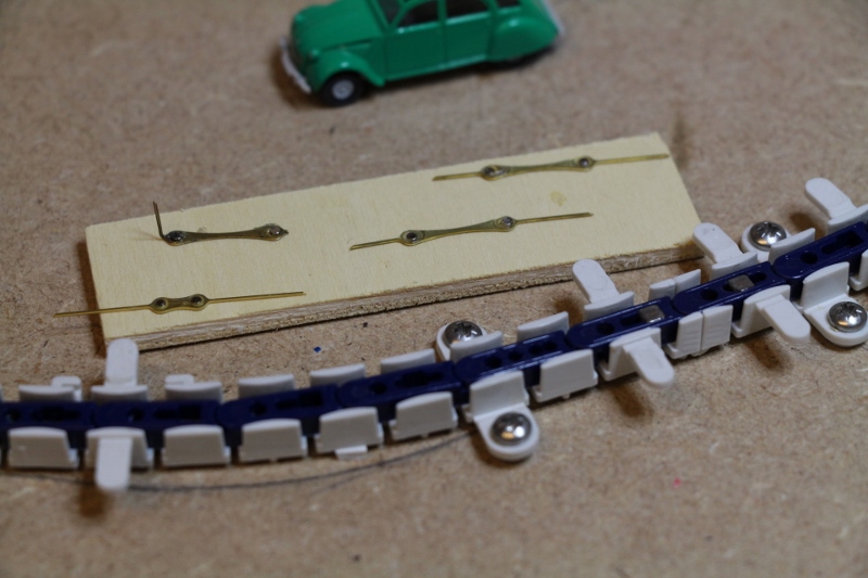
We can then glue the round micro-magnets on the sliders following this method:
- Place the cursor on the magnets embedded in the chain
- Add two dots of special metal glue, here I used Prince August
- Bring the magnet with a screwdriver and tanks to magnetism it will stick itself with the right polarity
We will now see how to cover the chain and move on to the implementation of this ingenious system.
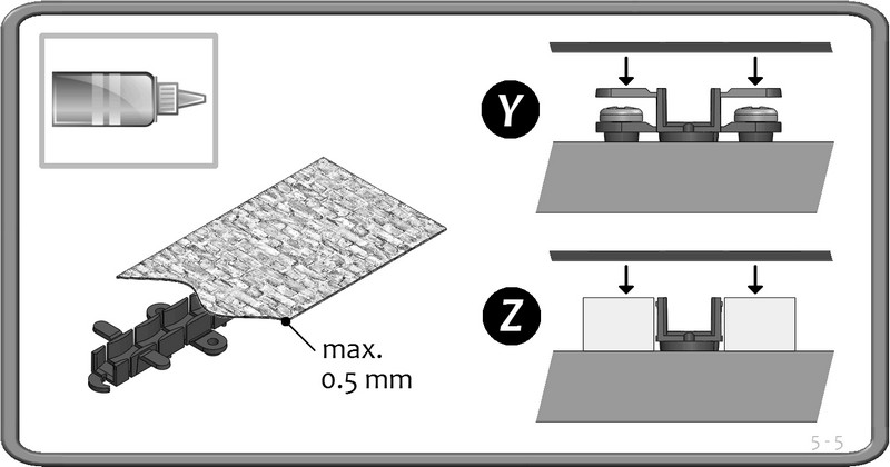
As explained in the instructions, the sheet used to cover the mechanism must not be thicker than 0.5 mm.
This sheet can be made of cardboard, paper, plastic card, PVC etc… but not metal!
It should not be embossed but perfectly smooth.
We will see that the joints between the sheets are the most sensitive parts but the number one priority for everything to work from the very first engine revolutions is to “press” the sheet against the track.
Two methods as illustrated in the leaflet:
- The sheet is glued to the small plastic tabs (Y)
- The sheet is glued to the edges of the relief in the case of a trench installation (Z)
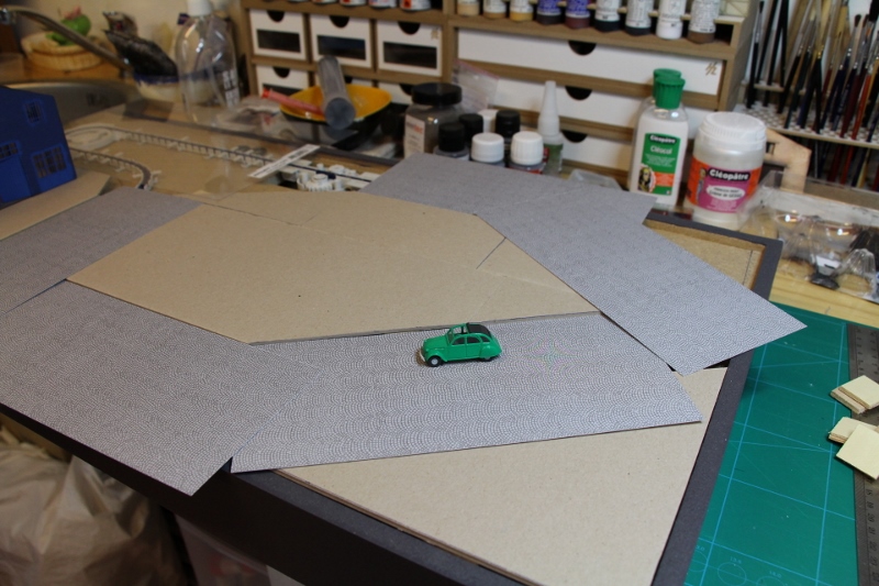
After laying grey cardboard sheets to fill in the areas around the track, I chose printed cardboard sheets from Auhagen ref 50111 imitation street paving to cover it.
They are thin (0.3 mm thick), very affordable and one set was enough to cover the whole track!
There are other colours in the Auhagen catalogue, such as concrete, bitumen…
Installation is relatively simple, but you must measure well before cutting to ensure that the joints between the sheets are perfectly joined and, above all, well plated. In this case, use the small plastic tabs or create new ones to secure the joints.
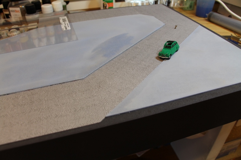
Before the final gluing, I advise you to apply two good coats of satin varnish (not matt) on the surface of each sheet to ensure a good durability of the drawing or the painting because the rubbing of the cyclist’s pad or the vehicle cursors tend to scratch and wear the surface. So a little precaution is needed here!
For the gluing I used Cléocol Cléopâtre glue.
All that remains is to power the engine before the cyclist’s first turns of the pedal! We are almost there!