How long can I make the track?
Actually, the track length is not limited. But for longer stretches, you have to use multiple motors to move the chain through the track. When using multiple motors, make sure the distances between the motors are more or less equal.
The most asked question on exhibitions is, what the maximum length of chain is that one motor can drive. There is no simple answer to this question. It depends on the friction of the chain in the track. Naturally; the less the friction, the longer the length… The friction depends on many parameters. The main factors are the number of curves; the variation in height; the covering material and the number of cyclists or car sliders used. It is really just basic physics of how much energy is needed to pull the load on the surface.
There is 2.25 metres (7.38 feet) track available in a starter set. The chain runs well with one motor on a not to curvy loop using 2 or 3 cyclists or car sliders. This length can even be extended to 2.50 metres (8.2 feet) when the loop is simple. And even a track length of 3 metres (10 feet) is possible, using a set of our return loops. The return loop is specially designed to experience very low friction in a 180° curve. This can be used effectively in a so-called dog bone shaped loop: That is – two straights with a return loop at either end. This gives you a two lane road and if you hide the return loops in a tunnel or behind scenery, it enhances the Magic of the vehicles travelling your highway!
Where is the best place to put the motor?
This question often arises when the chain does not turn properly or randomly, and this important point has not been sufficiently explained in our instructions, but we will work on it.
When you start to design your circuit you should think about the following points to define the best location for your motor.
- Do not install the motor near a curve or return loop.
- Put the motor preferably in the middle of your circuit, on a straight line. The length of the chain should be more or less equal on each side of the motor.
- Do not install the motor near a slope or downhill (at the beginning or end of the slope)
- The location of the motor should remain accessible from below for maintenance purposes and at best from above so that magnets can be added easily to the chain.
Can two motors be used on the same circuit?
Yes, absolutely, and the chain drive system has been designed to work with several motors.
This option is especially interesting for circuits with the following characteristics:
- Numerous bends, or very tight bends
- Long circuit length (over 2.5 m)
- Many vehicles to move (more than 4)
- Large vehicles to be moved (e.g. boats or large scale vehicles) with stronger magnets.
Care should be taken to ensure that the following points are observed:
- Distribute the chain length more or less equally between each motor
- Choose a motor with the same drive speed and of the same generation (since 2019 we have changed the torque of medium and high speed motors). To restate, they are not interchangeable with say an old medium motor and a new medium motor – a complete upgrade is needed. Also, when upgrading motors into the existing motor housing, only use the metal thread screws that came with your new motor as the early generation screws are too long and will damage the newer motors.
- Magnorail still stocks the older motor if you are wanting to extend your track without having to upgrade your motor – please contact us by email to confirm your older motor is still in stock.
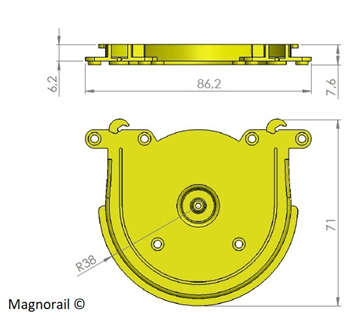
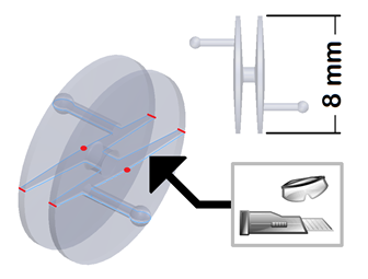
What is the overall size of the return loop?
This question comes up often and is understandable in order to integrate Magnorail without any problems.
The loop has a total width of 86 mm and allows a 180° turn over a diameter of 7 cm.
Its depth is about 7 mm (see attached photo).
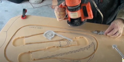
Can I insert the track (channel) into my baseboard ?
Yes, with advent of high-density foam boards into the hobby some people are removing all the supports and tags from the channelling and routing a path with their mini-tool like Dremel or router into the foamboard. This has the advantage of having a perfectly flat surface for your roadbed and also reduces potential warping or bending of the road surface.
You must ensure your router bit is set precisely to 8mm deep and preferably 8mm wide which will give the channel a snug fit. Some dovetail router bits whilst larger at the base, do have an 8mm cut at the top and this inserting method also helps reduce the track noise somewhat. Always do some test cuts and ensure that you can run your finger over the inserted channel without feeling it above the baseboard surface, otherwise it will show as a raised section on your road if the roadbed is material is thin. You can see some Videos from ou dealer in Australia MagnorailOz on Klatchco56 YouTube channel wich show this method in detail.
Can we make slopes, inclinations?
Yes, it is quite possible to make slopes and inclines, some modelers have even managed to create ski slopes with slalom.
If your track is completely sloped you can plan a reasonable 45° slope.
If your track is both flat and sloping you will have to be very careful with the part connecting the two areas. Indeed, no break is possible at this level because the chain was not designed for this, only a very slight curve will be tolerated, a bit like an arc. Ensure that the transition from slope to flat is moderated by doing “Super Elevation” on the channelling so that the curve eases from flat to slope
You will also need to provide one or more additional motor modules to distribute the drive forces of the chain with a motor in the middle of the top section and another in the middle of the bottom section or alternatively one halfway up the upward slope and also one halfway on the downward slope.
Is it possible to move large boats or vehicles (0 or 1/35 scale)?
Whilst the Magnorail system is agnostic to what is on the road surface, it was not designed to move heavy vehicles or larger scales. It does cope well with HO and OO diecast vehicles though as well as larger light boats plus any other vehicles or boats down to Z scale.
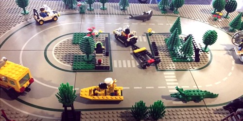
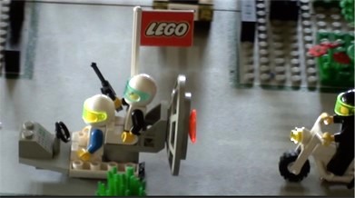
As example you can see some videos from our dealer in Australia on the MagnorailOz YouTube channel (klatchco56) showing Lego vehicles being easily driven on Lego baseboards by the Magnorail System. Also the system has been used on vehicles in the Lemax and Department
However, with a little imagination it is possible to move a larger vehicle if the following conditions are met:
- Plan ahead to move the chain with one or more additional motors
- Provide large curves for the vehicle’s wheels to turn without rubbing on the surface
- Provide for articulation of the vehicle’s front wheels when turning
- Finally, use larger magnets to avoid dislocation with the chain magnet.
- With larger vehicles or even smaller scales, using the reverse loops, you should try to hide the loops inside a building (Garage etc), cave, forest or off the main viewing area so the public do not see the actual turning vehicle which sometimes can be seen to be unrealistic and diminishes the Magic of the Magnorail system.
What to use as covering material?
This is the most frequently asked question and we will try to answer it in more detail:
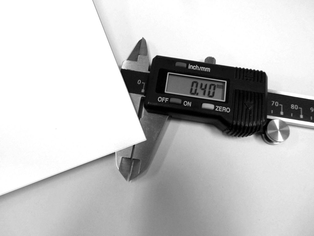
Generally speaking, you can use paper, cardboard or plastic in sheets, strips or rolls, but with a maximum thickness of about 0.5 mm.
You can use a higher thickness, but you will increase the risk of the magnets dislodging between the surface and the chain, especially on bends or uneven ground. Several tests will therefore be necessary before the cover is finally fixed to the track.
You can also use solid 350 gram paper, usually used for photography, but this is not the easiest to find.
In any case choose a dense material with a smooth surface that can be easily painted in the desired colour. After painting the surface, we recommend that you apply a coat of satin varnish to ensure a good glide.
Please also pay attention to temperature and humidity differences which can cause the surface of the material to swell.
For our demonstration module, we used Auhagen cardboard sheets ref 50111 and Maquett plastic sheets ref 602-02
Longer stretches without extra motors
Under normal conditions, the Magnorail track system requires a motor about every two and a half meters to overcome the overall friction.
When the track is meandering quite a bit, this might not even be enough, especially with multiple vehicles on the street. In that case the motor can start to slip. The disadvantages are of course added cost and the room required for these motors. The motors should be accessible from underneath and that might cause planning issues or alternatively the motors can be in a roadside building that the vehicles turn in to and then pass through, whilst the motor assembly could be lifted out if needed to do so. Clear matt sticky tape can be used on the joints of the removable section making sure the tape is flat with no edges to catch on !
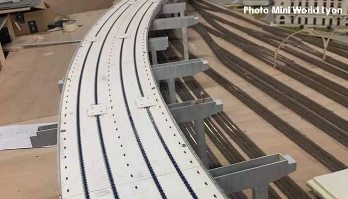
A solution is to use return loops for the tightest curves. As the wheel spins the friction will be nullified almost entirely.
Why do the track links have different letters on the sprue section when you open the starter pack?
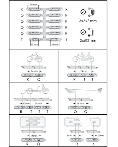
The links are coded mainly for the placement of magnets but also help you fine tune your track as mentioned in this page.
The standard bicycles need R x 1 and Q x 1. The ice cream vendor and cargo bikes need three track magnets (supplied) however they require an R + 3 T links to get the correct spacing to allow the bicycle and cart turn corners correctly. The instruction are on the inside lid of tin containing the ice cream vendor. You can also use spare links to tension the chain as needed. The tandem bike needs 1 x R and T x 2. Boats Q x 2.
This is an essential part of planning your layout and thinking of future use. You may not have a tandem bicycle or ice cream vendor at present but you should consider inserting an excess of track magnets in some different sequences for future vehicles and bicycles or even for just changing the placement of bicycles or vehicles in your daily running of the system, for a bit of variety!
My cyclist doesn’t pedal (correctly)?
Sometimes we get questions about bad (or not at all) pedalling of the cyclist. Usually these problems occur directly after the assembly of the cyclist. Once solved, its often solved definitely. Assembling the cyclist is not an easy job. The parts are very small and the technique of the rolling wheel requires a perfect connection of the components. If problems occur, these are often due to one of the following causes.
The transparent wheel is a very small injection molded part. This mould has to open to get the product out. So the transparent wheel does have a barely visible seam on the surface. Sometimes there is a small film left on the seam after the produt is ejected out of the mold. This film can hinder the wheel from rolling. The film can be removed with a sharp cutter blade.
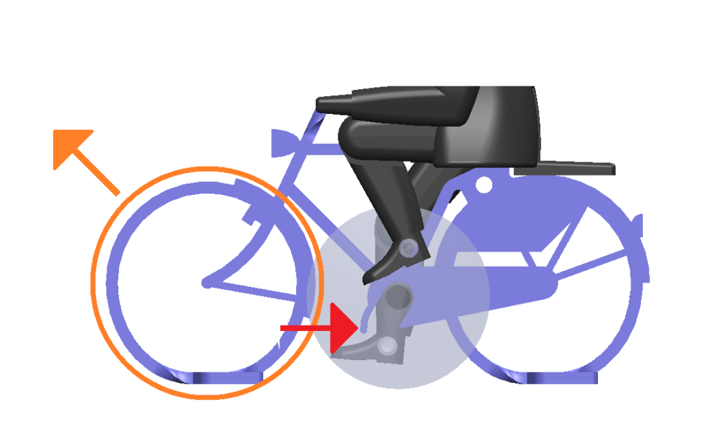
It’s possible the legs will bend back in the wrong direction when they can fully stretch. This occurs when the distance between the axis of the hip and the axis of the transparent wheel is too big. Sometimes it’s just a fraction of a millimetre… To reduce this distance, the wheel should be locked well (red arrow). If this doesn’t solve the problem, the front wheel can be bend a bit forward (orange arrow). Doing this, the axis of the transparent wheel will be closer to the axis of the hip when rolling on the surface. This will prevent the legs to be fully stretched.
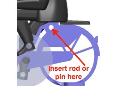
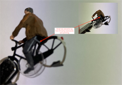
Another alternative to avoid the legs locking and flicking backwards, is to insert a small pin or piece of plastic into the bicycle frame to restrain the legs from doing that. The photos show where this pin on some older models comes preinstalled but also where to attach a pin if you are having this problem. The pin stops the thigh part of the leg from reversing its action. Loek (the inventor of Magnorail) said he couldn’t remember why they stopped inserting the pin but that aside, it is a fairly simple fix.
The cyclists make a squeaking sound…
If the bikes make a squeaking or grinding sound the first remedy is filing and sanding. Smooth the butterfly-shaped plates under the wheels as much as possible, for instance with the aid of a nail file. Because the material is etched it may have quite sharp edges.
Please check that the plates are in line. If not, the cyclist might totter on the street surface.
If the cyclist makes a singing sound, the front fork vibrates. Carefully bending it slightly usually helps here.
Finally, it may be that the road is too rigid. Coating the surface with a very thin layer of talcum powder can help to stop the sound.
The chain gets stuck and the motor doesn’t make it move.
This problem can be caused by too much friction in the chain, the length of the circuit for a single motor or too many vehicles being moved at the same time.
To ensure that the chain runs freely in the track, the following points must be observed:
- The chain should not be too tight or too loose but straight in the track (before and after the motor). It should not have a zig-zag pattern as this indicates too much slack. To make sure that the chain is running smoothly, simply remove the rubber seals (O rings) on the motor module and move the chain with your fingers. The chain should slide smoothly and without catching. If you notice a blockage, check the condition of the chain in the track and remedy the problem. Misalignment of the track for example, may occur if the channel track connectors have come apart slightly or not connected at all. If the chain is slack, fine tune the system by removing a link to “tighten” it or alternatively replace a Q, R or X chain link, with an S or T link. This may have to be done in several places until the chain has a smooth run without kinking or jumping out of the channel – which indicates that the chain is too tight.If you find your planned layout does not conform to the lengths of the supplied channelling, you can cut and join lengths to your requirements but ensure that the joins are perfectly aligned and secure with a flat piece of plastic underneath so the joints will not pull apart with use,
- The rounded end of each link that is cut from the sprue must be carefully filed down to achieve a force-free joint. This is a critical area and needs close attention to avoid jams between chain links.
- The circuit has too many turns or some of the turns are very tight. We recommend a radius of 8 cm for your turns, below this radius the chain friction will be high and you risk having the chain lock up. The number of turns is also an important point for a good circulation, if you have more than 4 turns think of using our reversal loops to replace some turns and you will decrease the friction.
- The length of the circuit may also be a factor, a motor can drive 2.5 m of chain in a circuit with several bends. See the part on the maximum length of the circuit.
- The circuit has too many vehicles or cyclists (more than 4). In this case, we advise you to add a new motor module to relieve the one already in place.
The chain gets stuck, lifts up and leaves the track
You can already repeat all the elements of the previous question concerning the blocking of the chain.
Concerning the lifting or “derailing” of the chain, this can be due to several reasons:
- The chain is too tight and slowed down in a turn. In this case, you need to add a half link to loosen the chain.
- The motor location is not centred but at one end of the circuit. In this case the motor can lift the chain at the other end. It will be necessary to change its location or reduce the length of the track.
- The wheel of the return loop becomes loose and the chain jumps. We recommend a piece of clear PVC or acetate sheet (like clear packaging material on the front of a carton) to cover the whole turning loop and secured with a countersunk screw in the middle, and this should hold the chain in place. The same goes for the motor module, which should preferably be covered during your tests. By covering the motor module and securing the PVC or acetate sheet with the four countersunk screws supplied with the motors, you will stop the chain from rising up as it passes through the O rings whilst driving the chain plus you do not have screw showing on the surface
Magnorail chain lubrication?
People sometimes ask whether or not the Magnorail track needs lubrication. This is not necessary, and may even render the system unusable. The drive uses rubber tires to move the chain, and any sort of lubrication will make these tires way too slippery.
Track Noise
The Magnorail System is not a silent operation, as the chain travelling through the plastic channelling does make a sound albeit a subdued background one. In any exhibition or public layout this becomes neglible.
People however, do report a clicking sound from the motor housing once they have installed everything.
This is attributed to the fact that they do not remove the sprue from the drive cogs correctly. Once you have cut the cogs away from the main sprue, you need to file all the teeth with a small angled file to remove sprue from between the cogs. You also need to file the underside where it was attached as this is a catch point. Pushing the cogs down too hard may also see the cogs catching on the motor housing if the cogs are not level. The O rings should be aligned at the same height otherwise the chain will rise out of the channel.
Upgrades in 2019 have made the motors much quieter whilst increasing their torque. Some enthusiasts have packed rubber or foam around the motors to further reduce any possible motor noise.